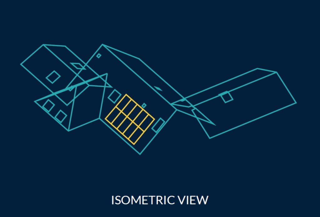
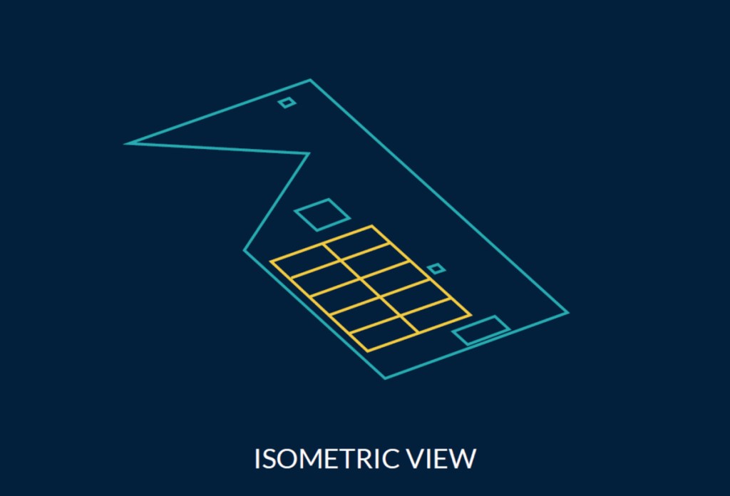
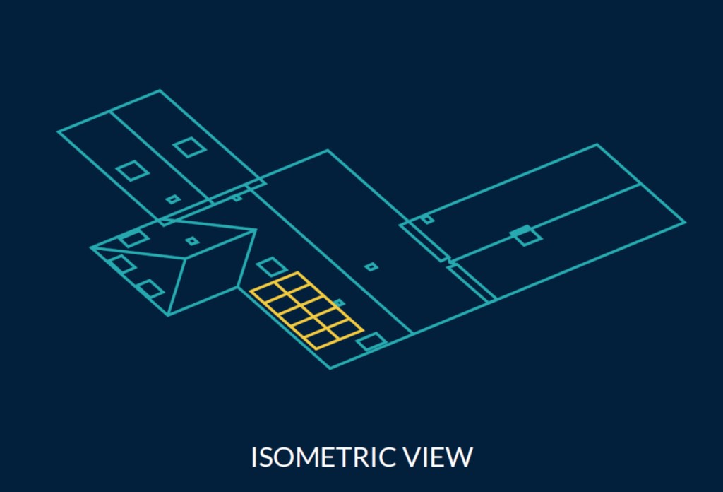
During the sales and planning phases of a residential rooftop solar project, different methods are used to figure out how to lay out the solar modules on a roof. We will talk about three methods that solar professionals often use during this phase.
 The Three Major Methods of Designing a Rooftop Solar System

Article from | EagleView
What are solar panel designs used for?
After a sale has been made, a solar design, also known as the “final design,” is completed during the planning stage to produce engineering drawings or the “plan set” for a project. These drawings are utilized to provide information on equipment selection, installation rules and permitting requirements.
What are the three types of solar design methods?
The three types of solar panel design methods are three-dimensional (3D), two-dimensional (2D) projected views and two-dimensional overlays.
Three-Dimensional (3D) Solar Panel Design
Certainly the most accurate in my opinion, 3D solar design methods leverage 3D models of structures, whether obtained from a third party or modeled by the user from field measurements, to perform solar module layouts. The solar module representations themselves are aligned to and placed on the 3D model, essentially creating a to-scale digital twin of the project in CAD. This methodology eliminates potential errors with adjusting solar module sizes to account for roof pitch, but does require a level of spatial ability by the designer to operate in a 3D environment. Because this method yields a digital twin of the structure, AutoCAD can generate many different views of the project to be included in the plan set such as, a holistic top-down view, 2D projected views or even 3D renderings.

Supported CAD Software: AutoCAD, SketchUp, and other popular CAD programs
Suggested CAD Software: AutoCAD
Suggested EagleView CAD Deliverable: Standard DXF file
Use Caution: When aligning the module representations to the roof facet to ensure the modules are not floating above the 3D roof facet as this may lead to accuracy errors.
Benefit: Speed, Accuracy, Consistency
Tip: To quickly and accurately place solar modules on a 3D roof facet, the “Align” command in AutoCAD is a single function that will move and rotate the solar modules in 3D space.
Two-Dimensional (2D) Projected View Solar Panel Design
As the more traditional method of solar design, 2D projected view solar design originated from when the most common practice to obtain roof measurements was sending a technician on the roof with a tape measure. These technicians typically provided perimeter measurements to the designer of each facet so that it can be redrawn in AutoCAD. While this method works very well to convert field measurements to a solar panel layout, some third party measurement providers do not provide CAD files in this format and furthermore, obtaining a top-down holistic view of the structure can be difficult to achieve (when configuring the location of each 2D roof facet to mimic the subject structure, the roof facets themselves do not match on each edge, much like laying an orange peel flat on a table-top).

Supported CAD Software: AutoCAD, SketchUp, and other popular CAD programs
Suggested CAD Software: AutoCAD or AutoCAD LT
Suggested EagleView CAD Deliverable: DXF file w/ 2D projected view
Use Caution: When forcing each roof facet projection together to obtain a holistic top-down view of the solar design as the roof geometries and the accuracy thereof can become compromised.
Benefit: The user and software can operate solely in a 2D environment
Tip: Instead of forcing 2D roof projections together to achieve a holistic view of the structure from the top-down point of view, EagleView’s new DXF file includes both a 3D model of the structure as well as 2D roof projections so that the designer can leverage either the 3D or 2D overlay methods to achieve the desired holistic plan view result while still being able to include 2D facet views in the plan set.
Two-Dimensional (2D) Overlays: The Hybrid Solar Design Method
Lastly, the solar design technique of a 2D overlay could be considered a hybrid of a true 3D design and the traditional 2D projected method. I believe that this methodology has gained in popularity amongst solar designers in recent times due to software limitations or the lack of professional CAD techniques developed all the way back when draftsmen were drawing by hand. Regardless of how it came about, this methodology can work nicely but does require the proper checks and balances in the designer’s process to ensure accurate results.

Supported CAD Software: AutoCAD, SketchUp, and other popular CAD programs
Suggested CAD Software: AutoCAD or AutoCAD LT
Suggested EagleView CAD Deliverable: Standard DXF file
Use Caution: When adjusting the solar module size to account for the sloped distance of the roof.
Benefit: Minimal CAD training is required for the solar designer to perform a solar module layout since they are basically drawing the view they want to see in the plan set
Tip: While EagleView delivers a 3D model in the standard DXF file, a 2D overlay can be performed directly on top of the model from the top-down view, or, the 3D model can be flattened in AutoCAD using the “Flatten” command (although, I do discourage the flatten practice as you will lose the sloped linear measurements we provide and the accuracy of the layout can be compromised)
Which solar panel design method should you use?
The best design methodology for your organization is dependent on your CAD software and the technical ability of the individual designer. EagleView recommends 3D solar design methods due to the speed, accuracy, and consistency they provide, but the 2D methods could work as long as the proper checks and balances are built into the designer’s processes to ensure accurate designs that can be installed on the subject roof. Regardless of what method your organization employs, EagleView can provide a CAD deliverable that will undoubtedly improve efficiency and accuracy.
The content & opinions in this article are the author’s and do not necessarily represent the views of AltEnergyMag
Comments (0)
This post does not have any comments. Be the first to leave a comment below.
