Current stretched porous film battery separators for lithium ion batteries are thin, strong, and provide a good barrier between electrodes, at the cost of having very high internal resistance and low ionic flow due to low porosity and high "dead space" that come from starting with a solid material and trying to impart porosity. This work uses an alternative approach, where linear nanofibers and microfibers are combined in wet laid nonwoven processes to give separators that are strong and thin, but have higher porosity (60-70%) and so have much higher ionic flow.
Brian Morin, PhD | Dreamweaver International
Introduction
Electric and hybrid vehicles are the most gasoline-efficient vehicles on the road today, and the best strategy to reduce our dependence on foreign oil and help achieve energy independence. They rely on lithium ion batteries to store the energy that is made in coal, gas or other power plants. To be widely adopted, those batteries must be safe and inexpensive.
Current lithium ion battery separators for electric vehicles are made from porous olefin films made either through the “wet technique” or the “dry technique,” based on whether they involve dissolving the polymer in solvent as one of the steps or not.
While these separators work well and control the lithium ion battery market, they are slow and their production is capital intensive and involves a lot of waste. Polypore has $334 million in capacity increases underway for their Celgard product, and Asahi Kasei has recently invested $135 million in capacity increases. Announcements from Asahi Kasei indicate that the capital cost is approximately
$2.50 – 3/m2 of annual capacity of material.
Dreamweaver International's (DWI) patent pending technology is based on a combination of microfibers and nanofibers. The microfibers provide scaffolding with high strength and an open structure, as can be seen in Figure 1.

Figure 1. Scanning electron micrographs (SEMs) of Dreamweaver separator, showing microfiber scaffolding and nanofiber separation material.
The nanofibers drape over the microfibers so the average pore size is low, and the pore size distribution is narrow.
Microfibers: Microfibers by themselves leave a pore size of at least several microns, much too large to be used in lithium ion battery separators.
Nanofibers: Nanofibers by themselves tend to blind, or have severely high resistance to the flow of liquids or ions. They also make extraordinarily weak webs, without the strength required in a high speed production process.
Combined: Combined, the material has the strength and openness of the microfiber scaffolding while the nanofibersdrape over the microfibers strategically, closing down the pore size and maintaining a high permeability to ions
Separator Testing
The pore size distribution is narrow with a center around 200-800 nanometers which can be controlled by varying the ratio of nanofibers and microfibers.
Basic properties of the separators are shown in Table 1, below. The materials can be made with thickness from 20 – 40 microns and have very low Gurley air resistance. The porosity can be controlled from 50 – 75%, and the pore size can also be varied by controlling the type of nanofibers and ratio of nanofiber to microfibers. The shrinkage is very low, giving good temperature stability up to 190 C. The materials look and feel like paper and have high strength and low elongation similar to paper, matching the physical properties of foils commonly used as current collectors.
Table 1. Separator properties of microfiber/nanofiber separator compared to film separators.

The separator was tested for thermo gravimetric analysis (TGA) from room temperature to 1000 C. The sample showed 1.39% mass loss, ending near 100 C, which is consistent with water loss from the cellulose fibers. The material showed no further degradation until approximately 300 C, when oxidation set in and a sharp decrease of approximately 60% mass between 335 and 400 C. The separator was also tested for differential scanning calorimetry (DSC) from room temperature to 300 C. There was a broad exotherm centered around 100 C, consistent with a release of water, and a sharper exotherm at 266 C consistent with the melting point of PET.
Cell Builds
High energy pouch cells were built by Polystor using NCM cathode chemistry with high loading (4 mAh/cm2) and carbon anodes for a total of 80 mAh. Additional cells were built at medium loading (2.5 mAh/cm2) with the same anode and cathode, for a total of 50 mAh. All cells were 4 x 5 cm in dimension and a single layer pouch cell. Cells were made with a Dreamweaver AC2030 separator as well as with Celgard 2325, a tri-layer separator that is 20 um thick. Comparison cells were made with Dreamweaver separator at 2.75 mAh/cm2 and 3.0 mAh/cm2.
Safety Testing
Cells made with 2.5 mAh/cm2 electrodes were tested under various safety tests in duplicate. Both the cells with the Dreamweaver separator and the cells with the standard separator passed all tests and otherwise performed identically. Fresh cells were used for each test.
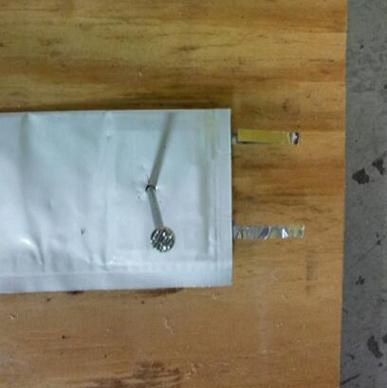
 Nail Penetration: The cells were pierced through the electrode stack with a nail and did not vent, smoke or flame, and the exterior of the cells did not go above 30 C.
Short Circuit: The cells were short circuited by connecting the positive and negative terminals with a copper wire with a resistance load less than 0.1 ohm. Cells did not vent, smoke, or flame and the exterior temperature of the cell did not exceed 30 degrees C.
Overcharge: The cells were charged to 4.2 volts at 1C. The cells were further charged raising the voltage limit by increments of 0.2 volts. The outside cell temperature was continuously monitored. When the cell types reached 5.1
V (standard) and 5.2 V (Dreamweaver) the temperature had raised to 55 degrees C, then the cell vented (without explosion or flame), and the voltage went to zero. Afterward the cell temperature lowered back down to room temperature.
Hot Box: The cells were heated to 150C in a circulating air oven at the rate of 5 degrees per min. The cells were maintained at 150 C for 10 min. Both types of cells did not explode or catch fire
Temperature Cycling: The cells were cycled through ten repeats of a 24 hour cycle that included 8 hours at 70 C, then 20 C for 4 hours, then 0 C for 8 hours, then 20 C for 4 hours. After this 10-day cycling, the cells were stored for 7 days. The samples, did not vent, leak, explode, or catch fire for both the standard separator and the Dreamweaver separator. Both types of cells were also tested for capacity and demonstrated close to 100% retained capacity.
Low Rate Cell Cycling & Self Discharge
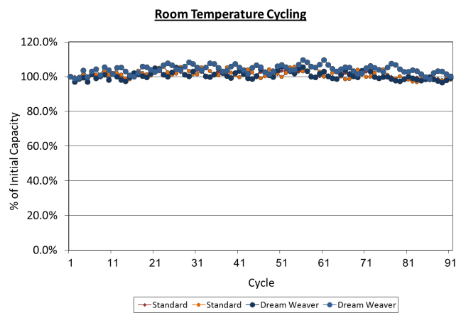
Cells made with 2.5 mAh/cm2 electrodes were tested for repeated cycles at room temperature at a C/5 rate. After
over 100 cycles, the cells made with the Dreamweaver separator and the standard separator performed identically and the capacity of the cells had not changed.

Figure 2. Room temperature cycling of cells made with Dreamweaver separator and standard separators show identical performance up to 100 cycles.
Cells made with 2.5 mAh/cm2 electrodes were tested for repeated cycles at 0 C and at 60 C at a C/5 rate. After over
30 cycles, the cells made with the Dreamweaver separator and the standard separator performed identically and the capacity of the cells had not changed.

Figure 3. 60 C and 0 C cycling of cells made with Dreamweaver separator and standard separators show identical performance up to 30 cycles.
Cells were also made and tested for self-discharge for 53 days. After being charged to 4.2 volts, the cell made with the standard separator had self-discharged to 4.106 V, while the cell made with the Dreamweaver separator had self-discharged to 4.059 V, a difference of 47 mV. This level of increased self-discharge is normal in comparing high rate separators to lower rate separators.
High Rate Tests
Cells with both 4 mAh/cm2 and 2.5 mAh/cm2 made with both Dreamweaver and standard trilayer PP/PE separators
were tested for discharge energy density at various rates.
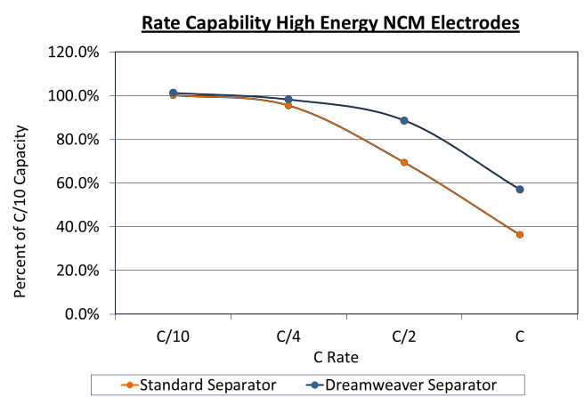
As can be seen in Figure 4 and Figure 5 below, at low rates the cells with different separators had similar capacities, but at higher rates the cells made with Dreamweaver separators tested to have higher energy density. The 4 mAh/cm2 cells had 58% more energy at a 1C rate, while the 2.5 mAh/cm2 cells had 80% higher energy at a 4C rate. A separator which demonstrates better capacity utilization at higher C rates will give a competitive advantage.

Figure 4. Rate capability of high energy (4 mAh/cm2) NCM electrodes. Cells made with Dreamweaver separator outperform cells made with standard separator above C/4.

Figure 5. Rate capability of medium energy (2.5 mAh/cm2) NCM electrodes. Cells made with Dreamweaver separator outperform cells made with standard separator above 1C.
While most testing has compared the Dreamweaver separator to dry processed trilayer separators, it is also important to compare to separators made from a monolayer of PP. In Figure 6, the Dreamweaver separator is used in a cell with 2.5 mAh/cm2 NCM electrodes and tested against both standard PE/PP trilayer separator as well as monolayer PP separators at both 16 um and 25 um thicknesses. The Dreamweaver separator gives higher energy density at all tested rates, with the 16 um dry processed PP separator coming closest in performance.

Figure 6. Rate capability of medium energy (2.5 mAh/cm2) NCM electrodes. Cells made with Dreamweaver separator outperform cells made with standard separator and cells made with 16 and 25 micron PP monolayer separators.
Higher Electrode Energy Loadings
Cell manufacturers normally design high rates with lower electrode thickness and increased electrode conductivity. As Dreamweaver separators achieve high rates without decreasing electrode thicknesses, it is interesting to explore
whether an increased energy density could be achieved by using higher coating thicknesses and reducing the amount of separator, current collector and electrolyte required to achieve the same overall total energy.

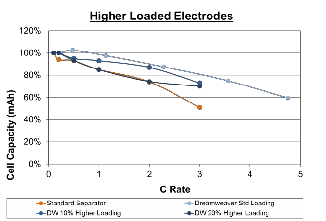
Figure 7. Rate capability of cells made with higher electrode loading (2.75 mAh/cm2 and 3.0 mAh/cm2). Cells made with Dreamweaver separator outperform cells made with standard separator at both higher loadings.
To test this, cells were made with the Dreamweaver separator at 2.75 mAh/cm2 and 3.0 mAh/cm2. The cells made with Dreamweaver separator at 10% higher loading outperformed the cells made with standard separator at all C rates. The cells made with Dreamweaver separator at 20% higher loading performed equal to the cells made with standard separator up to 2C rate, and outperformed above this rate.
Summary & Discussion
Nanofiber-based separators offer several advantages, including:
- increased wetting capability
- higher thermal resistance
- higher ionic conductivity
Safety testing in small 50 mAh pouch cells showed identical performance between cells made with trilayer PP/PE separators of 25 microns compared with Dreamweaver separators of 30 microns in several tests:
- Nail penetration
- Overcharge
- Short circuit
- Hot box
- Temperature cycling
Cells tested for cycles at room temperature, 0 degrees C and 60 degrees C also had performance that was equivalent. In self-discharge tests, the Dreamweaver separator allowed slightly higher self-discharge as expected for a higher rate cell.
The Dreamweaver separator delivered higher energy at faster discharge rates for all cell builds and in comparison to several different film-based separators. Based on this study, batteries that are made with Dreamweaver’s nanofiber-based separators can allow a higher power spectrum from the same batteries, allowing two advantages:
1. A battery can be built that will be able to address a much broader spectrum of discharge and recharge rates than with current polyolefin separators. While it hasn’t been tested specifically, the date here imply that cells could be recharged faster even if higher discharge rate is not needed.
2. A battery can be built to work at equivalent rates using far less separator and foil, and also less coating and winding times for the electrodes and battery construction. This would result in significant cost and weight savings.
Acknowledgements
The authors wish to thank Professor Gleb Yushin and Dr. Igor Kovalenko from Georgia Tech for the half cell tests, and Jim Kaschmitter and Steve Pierce at Polystor for the testing on full cell lithium ion batteries.
References
1. Kim, S. S.; Lloyd, D. R. J. Membr. Sci. 1991, 64, 13.
2. Bierenbaum, H. S.; Isaacson, R. B.; Druin, M. L.; Plovan, S. G., Ind. Eng. Chem. Prod. Res. Dev. 1974,
13, 2.
3. Jpn. Ind. News 1996, 91.
4. P. Arora, Z. Zhang, “Battery Separators,” Chem Rev
2004, 104, pp. 4419 – 4462.
5. http://www.asahi- kasei.co.jp/asahi/en/news/2010/e101028.html
6. http://www.asahi- kasei.co.jp/asahi/en/news/2007/e071127.html
7. http://corporate.evonik.com/en/content/product- news/lithium-ion-batteries/Pages/separion.aspx
8. http://www.lgcpi.com/lithium.shtml
9. http://www.leclanche.eu/separator.19.0.html
10. Robert Kostecki, Laura Norin, Xiangyun Song, and Frank McLarnon, “Diagnostic Studies of Polyolefin Separators in High-Power Lithium-Ion Cells,” J. Electrochem. Soc., Volume 151, Issue 4, pp. A522- A526 (2004)
11. Xiaosong Huang, “Separator Technologies for Lithium
Ion Batteries,” J Solid State Electrochem (2011) 15, pp. 649–662.
12. T.H. Cho, T. Sakai, S. Tanase, K. Kimura, Y. Kondo, T. Tarao, and M. Tanaka “Electrochemical Performance of Polyacrylonitrile Nanofiber-Based Nonwoven Separator for Lithium Ion Battery,” Electrochemical and Solid-State Letters, 2007, 10, 7, pp. A159-A162.
13. W. Xiwen, H. Jian, L. Ji, “Preparation Ultra-fine Fibrillated Lyocell Fiber and Its Application in Battery Separator,”
14. Int. J. Electrochem. Sci., (2011) 6, pp. 4999 – 5004.
15. P. Arora, S. Frisk, L. Zhang, “Batteries Including
Improved Fine Fiber Separators,” US Patent
7,112,389.
16. D. Ensor, H. Walls, A. Andrady, T. Walker, “Particle
Filter System Incorporating Nanofibers,” US Patent
7,789,930.
17. V. Kalayca, D. Crofoot, T. Grafe, K. Graham, “Reduced Solidity Web Comprising Fiber and Fiber Spacer or Separation Means,” US Patent 7,717,975.
The content & opinions in this article are the author’s and do not necessarily represent the views of AltEnergyMag
Comments (0)
This post does not have any comments. Be the first to leave a comment below.
Featured Product


