Many new installations benefit from solid core transformers, and split core technology is not designed to compete with these. However, existing machines and building equipment have no way to add solid core devices without a costly shut-down of the system. New materials and technologies equip advanced split core current transformers for immediate retrofitting of high-performance and cost-effective condition monitoring, power metering and facility supervision systems.
Pierre TURPIN | LEM Energy & Automation division
Abstract
Electrical power calculation involves current measurement with specific electrical and mechanical characteristics according to the different application areas. While solid core current sensing technology has been able to provide good performance at low cost for a while, some split core sensor technologies have recently made big progress reviving their value for applications involving the retrofitting of power meters into existing equipment. Split core current transformers are not new, but in the past they were bulky and heavy, implementing conventional technologies that presented numerous shortcomings. These transformers either implemented expensive materials, or provided poor performance in terms of accuracy. In this case, inaccuracy refers not to the readings themselves, but to the linearity, the phase shift error of the output current and the sustainability of a reading over time. The following article provides an analysis of the traditional current sensing technologies and some innovative ones, highlighting their advantages and drawbacks in different power measurement application areas.
Power measurement applications
Electrical power measurement is already at the heart of numerous applications in the industrial sector for 1) power supply management, 2) electricity usage control and 3) condition monitoring.
1) Power supply management is the primary application field as it is essential to any industrial and business activity. It mainly concerns companies related to power generation and distribution, but also industry professionals monitoring their power quality and power factor to control rate tariffs imposed by their utilities, especially when operating low-power-factor loads.
2) Energy sub-metering is gaining importance among facility and plant managers as it allows tracking and allocating energy costs, but also performing advanced analysis of the electricity consumption to improve its efficiency. Power supply sizing and billing is often dependent on the peak consumption and a dynamic management of the overall system enables both cost reduction and failure prevention. Energy sub-metering is required for understanding and managing the main consumers, but also for identifying the energy wastes that are generally caused by defective appliances or inefficient facilities usage (e.g. inappropriate lighting, heating or air conditioning).
3) Condition monitoring requires immediate failure detection and reaction to prevent damage to equipment or interruption of critical processes. Electrical power measurement provides a comprehensive set of information (current, active power, power factor, frequency, etc.) that reflects the motor load behavior (e.g. conveyer, bearing, pump, cutting tool, etc.). It often provides faster detection of abnormal behaviors than traditional sensors such as temperature, pressure, vibration, etc. An analysis of the evolution in time of these electrical parameters even enables the anticipation of failures which allows for planning effective predictive maintenance.
Power measurement is not only gaining importance in industrial applications, but also for monitoring commercial and residential loads. Energy conservation is a rapidly growing issue across the globe, for both cost and environmental considerations. The key question is – how can a substantial and sustainable reduction of energy consumption be achieved? The most credible solution is to establish an understanding of how users consume their energy and make them responsible for it. Targeting this area remains an industrial concern and is gaining importance for the public sector. Many countries are introducing campaigns and incentive budgets for reducing energy consumption. Taking advantage of such incentives requires organizations to develop accurate measurement capabilities.
Current sensor requirements
Engineers designing power monitoring systems should carefully select the required current sensors according to very specific characteristics:
1. Accuracy - In most applications, measurement accuracy directly impacts the efficiency of an overall system. The accuracy of the power calculation is obviously dependant on the accuracy of the current sensors. A class 1 power meter will require current sensors with much better than 1% accuracy, which would generally involve expensive materials and manufacturing processes. An alternative is to calibrate the power meter for each single sensor it implements. Taking into account the specific characteristics of each sensor allows for use in its most precise operating mode and to mitigate the variations from one sensor to another. As we will see later in this article, this opens the door to new technologies with outstanding performance in terms of linearity, drift and repeatability, compensating for their overall loose reading.
2. Drift - The drift of a sensor is related to the sustainability of a reading over time independently from the initial system calibration. Some variations of its characteristics may be caused by changes in the ambient humidity and temperature, component aging, etc. A low drift level - meaning that the sensor has a high immunity to such constraints - is a very important characteristics to build high-performance, stable and reliable power meters.
3. Linearity - The linearity of the sensor refers to the stability of its characteristics within the full operating mode. A high linearity of the analogue sensing part is essential to provide accurate measurement of a wide range of primary currents, especially at low current levels. Several technologies only offer good performance over a limited measuring range, thus limiting the application area to rather high or low currents.
4. Phase shift - The accuracy of the true active power or energy calculation is not only related to the accuracy and linearity of the AC current and voltage sensors in terms of amplitude, but also to the phase shift that may occur between the measurement of these correlated values. The phase shift should of course be as low as possible.
5. Integration - Being self powered, the current transformers do not require any other wiring than a 2-wire output connection to the main power monitor unit. Many of them provide calibrated standard outputs allowing easy integration in the power monitoring system. The typical 1A and 5A or 333mV outputs are compatible with most standard power meters of the market. High accuracy power meters require specific calibration according to each sensor that cannot be interchanged anymore. These may then have low current outputs that are safer than traditional 1A / 5A signals when they can be accessed while the system is operated. Current outputs are also almost insensitive to interferences and should be preferred to voltage outputs when long cables are required to connect the sensors to the power meter.
6. Price – The price of the sensors is important of course, especially when 3 accurate current sensors are required for 3-phase power measurement. However, the price of the current sensor should not be considered alone, but also the installation and maintenance costs. Although more expensive, reliable and easy to install and replace split core sensors bring real cost reduction to the system as a whole.
Solid core current transformers
Power measurement systems generally implement contactless current sensors rather than shunts, because the latter cause power losses as well as installation and safety issues. Traditional solid core current sensors are based on the principle of a transformer, i.e. primary and secondary windings magnetically linked by a core. The measured current induces a magnetic field in the core which generates a current in the secondary windings proportionate to the primary current divided by the number of turns of the secondary windings. These basic current transformers are designed to measure sinusoidal alternating currents in the typical 50/60 Hz range. This well known technology is very affordable due to the use of common materials and processes.
Solid core current transformers offer a cost-effective and accurate solution for designing power meters dedicated to new equipment and buildings. They are not suitable, however, for the numerous applications involving power monitoring of existing machines and facilities, where it would be necessary to shut down power and disconnect cables before retrofitting the solid core sensors in all the places where they might be used. Installing power metering systems is generally not possible, prohibitively expensive or even dangerous if it requires a service interruption, even for a short while (e.g. stopping a production line, a telecom or datacenter power supply, some nuclear plant equipment, etc).
Split core current transformers
Contactless self-powered split core current transformers can simply snap over a conductor, without the need to screw or weld on complex brackets, making installation and maintenance straightforward. They can be installed in electrical control panels – thus avoiding complex wiring – to remotely monitor devices that sometimes operate in inaccessible or harsh environments. The beauty of the split core transformers is that they can be retrofitted into a live installation without disturbing it, which often make them the unique choice for engineers designing power meters.
But these advantages have a price, making the split core current transformers more expensive and less accurate than the solid core transformers. It is thus very important to understand the difference between the various technologies available, and make a choice according to specific application constraints.
Split core current transformers are generally based on the same principle described above for the solid core transformers. But in this case the magnetic core is made of two distinct parts that can be separated. Inaccuracy mainly comes from the imperfect contacts between the two parts, and the fact that the secondary windings are not uniformly distributed around the magnetic core, but around one of the two parts only. The price and performance of these transformers are linked to the physical and mechanical characteristics of the device. Very flat contact surfaces are required as well as sufficient pressure between the two parts of the core. The case generally features flexible parts or materials and/or hinges to provide sufficient compression as well as a reliable opening mechanism.

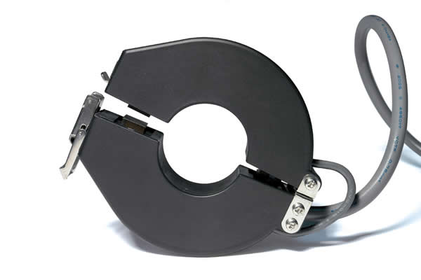
Fig. 1: A split-core current transformer (1000A)
FeSi split core current transformers
FeSi has been widely used in split core current transformers, mainly due to its affordable price. The performance offered by this material is quite bad, however, especially due to its poor linearity (especially at low currents) and the large phase shift (a typical characteristics is represented on figure 1). This restricts its use to low-cost current transformers for measuring rather high currents, where power monitoring doesn’t require high accuracy. Many applications only need a rough estimation of the power consumption, rather for detecting the electricity consumers than for analysis their exact consumption. This may be sufficient in some cases to detect whether a device is consuming electricity or not, and to draw operating time profiles, assuming a fixed voltage value rather than using a precise measure. In this case the high phase shift is not a big issue. A typical application is branch current monitoring in panel boards allowing a system to detect when some circuits may come to overload and generate an alarm or balance loads.
Another disadvantage of FeSi current transformers is that they are large and heavy, thus not very appropriate for environments with limited space.
FeNi split core current transformers
FeNi has been the best material for split-core current transformers for a long time, offering good performance, but at high price. It offers a good alternative to the FeSi material when accuracy and phase shift are important, or when the transformers need to measure small currents.
Apart from the price, FeNi current transformers have some other limitations. As for the bulky FeSi current transformers, they are taking up valuable space within industrial facilities and panel boards. They also suffer from quite bad linearity and drift, mainly due to the air gaps induced by the split core architecture.
Ferrite split core current transformers
Although ferrite materials have been well known for years, their poor performance in terms of saturation level and magnetic permeability did not allow their use at frequencies as low as 50/60Hz. However, recent developments have revolutionized the characteristics of ferrite at these frequencies, bringing many advantages to a wide range of power monitoring applications. The new types of ferrite have significantly improved permeability and can be implemented in 50/60 Hz current transformers as a substitute for FeSi or FeNi cores, despite the low magnetic saturation level.
Split core current transformers implementing the new types of ferrite can perform accurate measurement of AC signals in an extended frequency range that includes the 50/60 Hz application domain. They take advantage of the intrinsic ferrite qualities, providing high accuracy and excellent linearity even at very low current levels. They also feature particularly low phase-shift between input and output currents, which is essential to accurate measurement of true active power or energy. The hard and dense core allows for the minimization of air gaps and is virtually insensitive to ageing and temperature changes in contrast to other materials like FeSi or FeNi.
Last but not least, all the ferrite qualities are available at low cost, which puts the high performance split core current transformers on the market at very attractive price.
With high currents, bigger ferrite cores should be used for measurement, which are unfortunately rare for now due to some fabrication limitations. FeNi transformers or the Rogowski Coil technology described below are actually more appropriate for high currents.

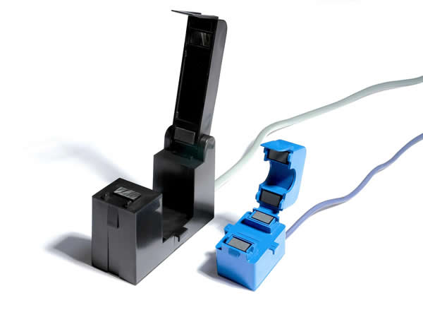
Fig. 2: A 800A ferromagnetic split core current transformer and a 100A ferrite split core current transformer
Comparison between FeSi, FeNi and Ferrite materials
The high-permeability ferrite material does not give the best results in solid-core current transformers, so let us focus on split core current transformers. The hardness of the solid material (consider ferrite as a ceramic) allows very fine machining, providing air gaps down to a few microns that are stable over many years. Laminated materials such as FeSi or FeNi do not allow air gaps smaller than 20 or 30 microns, and these are more sensitive to ageing and temperature changes. Add the small air gaps to the better linearity of the ferrite at low magnetic excitation (i.e. for low current), and the ferrite offers a better performance than FeNi-80%, and a lower cost.
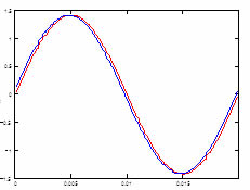
Figure 3 -1, 3-2 and 3-3 are extracts from simulations comparing the phase shift behaviour of FeSi, FeNi and high-permeability ferrite in a 5A current transformer.
 |
Ip = 20% of rated current F = 50 Hz Core: FeSi Air Gap = 25mm (one leg) Results:
|
 |
Ip = 20% of rated current F = 50 Hz Core: FeNi-80% Air Gap = 25mm (one leg) Results:
|
 |
Ip = 20% of rated current F = 50 Hz Core: Ferrite Air Gap = 5mm (one leg) Results:
|
Fig. 3: phase shift behaviour of FeSi, FeNi and high-permeability ferrite in a 5A current transformer
The phase shift for the ferrite is half that of the FeNi core, so FeNi is definitely out of the competition. The reduced air gap of the ferrite core also allows a better accuracy of transfer ratio (primary turns to secondary turns).
Rogowski coils
A Rogowski Coil is used to make an open-ended and flexible sensor that easily wraps around the conductor to be measured. It consists of a helical coil of wire with the lead from one end returning through the center of the coil to the other end, so that both terminals are at the same end of the coil. The length is selected according to the relevant current measuring range to provide optimal transfer characteristics.
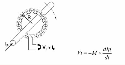
This technology provides a very precise detection of the rate of change (derivative) of the primary current that induces a proportionate voltage at the terminals of the coil. An electronic integrator circuit is required to convert that voltage signal into an output signal that is proportional to the primary current. In other words, the Rogowski Coil enables the fabrication of very accurate and linear current sensors, at the price of additional electronics and calibration.
A Rogowski coil has a lower inductance than current transformers, and consequently a better frequency response because it uses a non-magnetic core material. It is also highly linear, even with high primary currents, because it has no iron core that may saturate. This kind of sensor is thus particularly well adapted to power measurement systems that can be subjected to high or fast-changing currents. For measuring high currents, it has the additional advantages of small size and easy installation, while traditional current transformers are big and heavy.

Fig. 4: Rogowski Coil principle
The performance of such current sensors highly depends on the manufacturing quality of the Rogowski Coil, since equally spaced windings are required to provide high immunity to electromagnetic interference. Another critical characteristic is the closing point that induces a discontinuity in the coil, creating some sensitivity to external conductors as well as to the position of the measured conductor within the loop. The locking or clamping system should ensure a very precise and reproducible position of the coil extremities, as well as a high symmetry while having one of the extremity connected to the output cable. Some new technologies have recently appeared in this area, with special mechanical and electrical characteristics that allows much better accuracy and immunity to the primary cable positioning. While the error due to primary cable position was typically not better than +/-3% in the 50/60 Hz frequency domain, it has been reduced to less than +/-0.5% on some of the latest Rogowski Coil sensors.
Fig. 5: A Rogowski Coil current sensor from LEM
Conclusions
Many new installations benefit from solid core transformers, and split core technology is not designed to compete with these. However, existing machines and building equipment have no way to add solid core devices without a costly shut-down of the system. New materials and technologies equip advanced split core current transformers for immediate retrofitting of high-performance and cost-effective condition monitoring, power metering and facility supervision systems.
The fast growing energy efficiency market and the large deployment of power measurement systems dictate the need for high performance but cost effective split core current transformers.
Split-core current transformers are not new, but conventional technologies used in these transformers presented numerous shortcomings. These transformers either implemented expensive materials (e.g. FeNi), or provided poor performance, especially in terms of linearity and phase-shift (e.g. FeSi). New types of ferrite with dramatically improved magnetic permeability finally achieved to offer both high performance and affordable price. The Rogowski Coil technology has also made big progress recently, allowing small, light and flexible sensors for high currents, but requiring some signal adaptation and calibration to take advantage of the best of its characteristics. The major improvements that have been made in the designs and manufacturing processes have allowed to reduce both the cost and the sensitivity to the Coil positioning around the primary cable, thus overcoming one of the main problems of that technology whose intrinsic qualities were very interesting.
The multiplicity of the technologies responds to the diversity of the needs for an application domain that has evolved a lot recently, to address the diverse systems and infrastructures impacted by cost and environmental considerations.
Author:
Pierre TURPIN, Project Manager for LEM Energy & Automation division
Pierre TURPIN has an Engineering degree in Electricity from the French Engineering University in LYON. In 2003 Pierre joined LEM as development engineer and later as Energy & Automation Project Manager.
The content & opinions in this article are the author’s and do not necessarily represent the views of AltEnergyMag
Comments (0)
This post does not have any comments. Be the first to leave a comment below.
Featured Product


